Reinforcement: Lap Splices in Masonry
Reinforced masonry provides excellent resistance to compression loads, and relies on embedded reinforcement to resist tension forces. Vertical and horizontal rebar carry these tension forces to the foundation or other structural supports. When reinforcement is discontinuous, lap splices are used to transfer tension from one bar to the next. Lap splices are commonly seen at foundation dowels, with low lift grouting, in joint reinforcement, and in bond beams near building corners.
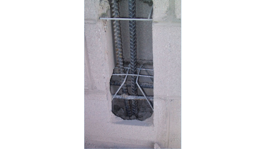
Two adjacent bars at a non-contact lap splice, held in position during grouting by a galvanized wire rebar positioner placed in the mortar joint.
Lapped bars may be placed in contact with one another, as shown on the left in the Figure below, but bars do not need to be tied together or even touching to transfer force. Tension force is transferred not by contact between the bars but through the surrounding grouted masonry. The TMS 402 Building Code Requirements for Masonry Structures actually permits non-contact lap splices (right image in Figure), as long as the bars are separated by less than 1/5 the lap length or a maximum of 8 inches. Lapped bars placed in adjacent grouted cells will usually meet these requirements.
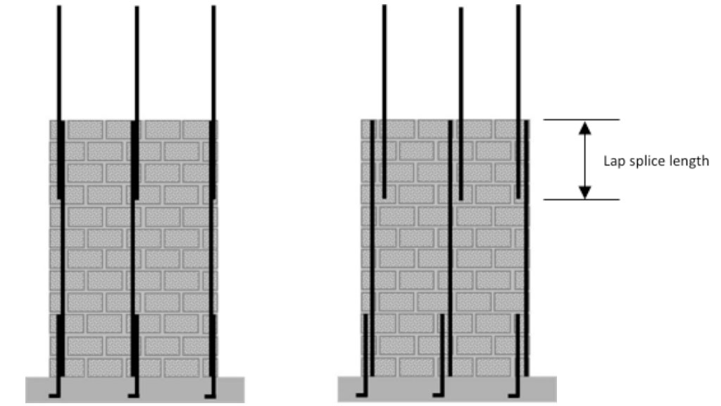
Contact lap splices (left). Non-contact lap splices (right).
The required lap splice length is calculated according to the TMS 402 Code and varies depending on material properties and bar size.
- Bar diameter: longer lap lengths are required for larger diameter bars.
- Rebar yield strength: longer lap lengths are required for stronger steel.
- Masonry design compressive strength f’m: lap lengths are shorter for stronger masonry.
- Cover distance: longer laps are required for bars placed at the face shells; lap lengths are shorter for bars centered in walls.
The masonry design code considers several different failure modes including bar yield and fracture, bar pullout, and masonry splitting. The lap lengths required by code are long enough to prevent pullout, and the failure mode usually shows as tensile splitting cracks along the length of the lap as shown in the Figure below.
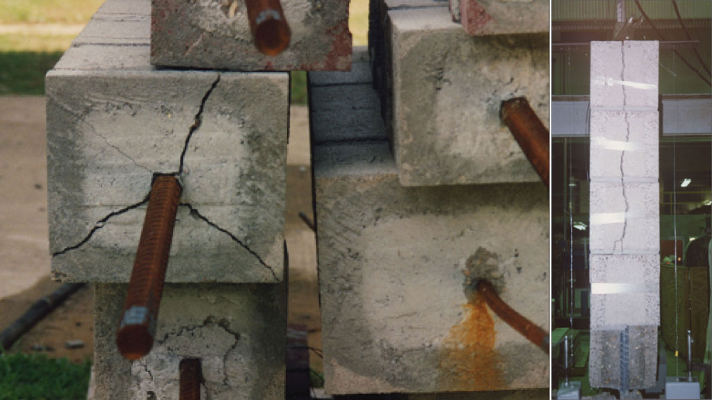
Tension tests on lap splices with reinforced masonry. When tested to high loads, laps usually fail by developing tension splitting cracks along the length of the lap.
Some contractors use mechanical splices when the design calls for large diameter bars (where lap lengths are very long) or to prevent congestion in heavily reinforced walls. The TMS 402 Code permits mechanical splices but they must be capable of developing 125% of the bar yield strength. Rebar may also be welded if acceptable to the engineer, but special welding procedures are required including pre-heating, cleaning, and special inspection according to American Welding Standard AWS D1.4. ASTM A207 grade rebar is easier to weld and has less restrictive pretreatment requirements than normal ASTM A615 rebar.