Reinforcement: Adding Reinforcement to CMU Walls Under Construction
Words: David AbelSo, the special inspector just let you know that you missed installing a couple of vertical reinforced cells in your CMU walls or maybe one cell got reinforced and grouted to a certain height in the wall but was only grouted from there to the top of the wall. Whoops, what now? Fortunately, there are ways to add the required reinforcing steel without having to tear the wall down and rebuild.
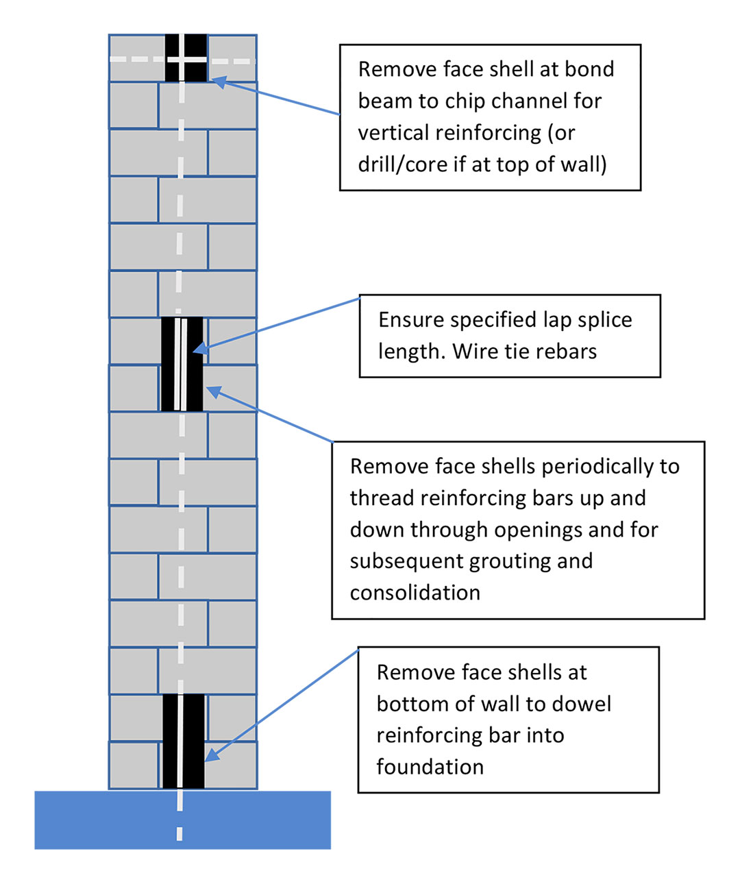
Adding reinforcing steel in ungrouted cells is relatively straight forward. However, bond beams in the wall will complicate the installation. Keep in mind that the specified lap splice length will apply to the added reinforcing steel and may determine how often openings are needed in the wall to “thread” in reinforcing bars. In general, the process is to remove face shells on the vertical cell to be reinforced at the base of the wall, at bond beams and periodically to thread bars into the wall to achieve the required reinforcing and lap splice lengths (Figure 1).

Figure 1. Steps for adding reinforcing in completed walls.
The engineer of record should advise on the required embedment depth and anchorage method for the foundation dowel. Once all reinforcing has been placed according the project requirements, the cell at the lowest opening should be cleaned of mortar droppings and these face shells reinstalled. After the mortar has cured, grout can then be placed, consolidated and reconsolidated from the next highest opening in the wall. Once the grout has cured sufficiently, the next set of face shells can be reinstalled, and the process repeated up the wall. The grout in intermediate bond beams will have to be chipped out to allow placement of the new vertical reinforcing. This will have to be done carefully to avoid damaging the horizontal bond beam steel. Complying with minimum grout space requirements of TMS 602, Specification for Masonry Structures, may require removal of considerable grout at the bond beam. As an alternate, consult with the engineer of record to see if dry packing with a non-shrink grout is acceptable once the reinforcing has been placed. This would be done only at the location of the bond beam. Lastly, if the bond beam is at the top of the wall, your engineer may or may not require continuing the vertical reinforcing through the bond beam.
We have also encountered situations where the vertical reinforcing was inadvertently left out above or below a certain height in the wall. The cell was grouted full height, but the reinforcing is only partially present. It is possible to remove face shells and cut a trench for supplemental reinforcing and regrout, but this can be time consuming and will affect wall aesthetics. This may be the only option if the CMU wall is fully grouted. Fortunately, TMS 602 allows something called a “noncontact lap splice” where the supplemental bar can be up to 8 inches away (in an adjacent cell). The exact language states: “Position bars spliced by noncontact lap splices no farther apart transversely than one-fifth the specified length of lap nor more than 8 in. (203 mm)”. Typical rebar sizes such as #5 will have required lap lengths of 16-20 inches so one-fifth the specified lap length would only allow up to a 4-inch transverse offset. Increasing the lap length to 40 inches in these cases only would allow placing a supplemental vertical reinforcing bar in an adjacent cell and meet the TMS 602 requirement. Again, placement of the supplemental reinforcing should be in compliance with the project requirements. As with adding full height reinforcing (discussed above), doweling into the foundation may be required and placement of vertical reinforcing at bond beams will have to be handled in a comparable manner.
References
TMS 602-16, Specification for Masonry Structures (Formerly also designated as ACI 530.1 and ASCE 6)