Anchors, Connectors, and Fasteners: Veneer Anchors for Larger Cavity Widths
Words: David AbelThe cavity width behind masonry veneers has been steadily increasing, primarily due to newer energy codes promoting continuous exterior insulation in building envelopes. With 2 to 4 inches of rigid insulation installed in the cavity, the distance from sheathing to the back of the veneer can easily be 5 inches or more. Veneer anchors (also commonly called “ties”) need to be capable of the increased structural demand from larger cavities. Since veneer anchors need to resist loads that are both towards and away from the backup, the anchors will need to perform adequately in compression and tension. Light-gauge anchors are likely to buckle when subjected to compressive loads, so more robust anchor systems are necessary for larger cavity widths.
Let’s look at the available veneer anchors that are recognized by the 2016 Building Code Requirements for Masonry Structures (TMS 402) and review which ones can be used with various backup materials. Most of the following material is from Chapter 12, Veneers, Section 12.2.2, Prescriptive requirements for anchored masonry veneer of TMS 402. Table 1 provides a summary of anchor type and backup compatibility.
Table 1. Anchor types allowed per backing by TMS 402 | | Backup Type |
| Anchor Type | Wood Stud | Metal Stud | Concrete | Masonry |
| Corrugated sheet-metal | ✓ | | | |
| Sheet-metal | ✓ | | | |
| Wire | ✓ | | | ✓ |
| Joint reinforcement | | | | ✓ |
| Adjustable | ✓ | ✓ | ✓ | ✓ |
Adjustable anchors can be used for all backup types and we can see that corrugated sheet-metal and sheet metal anchors are only to be used with wood stud backup. These last two types of anchors are often mistakenly used with a masonry backup.
Anchor choice is sometimes dictated by the type of wall construction. If spray foam insulation is specified in the cavity, adjustable anchors plates or joint reinforcing with eyes are typically used and the foam installers use the plate or wire to gauge the thickness of the foam. With multi-story wood backup and clay masonry veneer, adjustable anchors are necessary to accommodate the differential movement that will occur between the backup and the veneer.
For cavities wider than 4 5/8 inches, joint reinforcing (with or without adjustable anchors) and adjustable anchors are the only anchor types prescribed by TMS 402 and they are currently limited to a maximum cavity width of 6 5/8 inches. For cavity widths wider than 6 5/8 inches or for other anchor systems not prescribed by TMS 402, the building official may require engineering calculations or laboratory test results confirming that the anchors have the required strength and stiffness. The Brick Industry Association (BIA) recommends in Tech Notes 44B, Wall Ties for Brick Masonry, that the anchor be subjected to an axial load of 100 pounds in tension or compression with a maximum allowable deflection of 0.05 inch. Adjustable ties have an inherent deflection of 1/16 (0.06) inch due to the allowable mechanical play. As a result, the BIA recommended deflection limit should apply at the expected maximum eccentricity (in use), once the mechanical play has bottomed out.
Anchors should be embedded into the mortar joint of the veneer for a minimum distance of 1.5 inches and have a minimum cover of 5/8 inch to the outside (weather) face of the veneer. Mortar joints should be twice the thickness of the embedment portion of the anchor, meaning that the largest practical wire size for anchors is W2.8 (3/16 inch Ø), with typical 3/8 inch mortar joints.
The prescriptive anchor spacing will vary by the type of anchor but note also that locations with high winds or seismic activity or anchors around openings will have different spacing requirements. Designers intent on maximizing the thermal performance of the exterior walls will use the largest possible spacing with stainless steel or coated anchors to minimize thermal bridging.
Lastly, with all anchor types, TMS 402 requires that a minimum 1-inch air gap be specified. Many design professionals specify larger air gaps (1½ to 2 inches) to promote drying of the cavity and as added insurance against construction deviations, mortar fins and droppings that can decrease the specified air gap.
Table 2 provides a more in-depth view of the proper application and limitations of the various anchor types.
Table 2. Anchor types with limits imposed by TMS 402 | Anchor Type | Limitations |
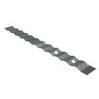
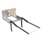
1. Corrugated Sheet Metal | - 1” cavity max. from inside face of veneer to outside face of sheathing.
- For wood backup only.
|
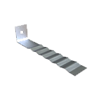
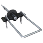
2. Sheet Metal | - 4 5/8” cavity max. from inside face of veneer to stud
- For wood backup only
|
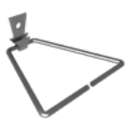
3. Wire | - 4 5/8” cavity max. from inside face of veneer to stud or outside face of backing
- For wood and masonry backups only
|
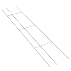
4. Joint Reinforcing | - 6 5/8” cavity max. from inside face of veneer to outside face of backing
- Cross wires at max. 16” on center
- For masonry backup
- For cavity widths exceeding 4 5/8”, cross and longitudinal wires must be min. wire size W2.8
- When used with adjustable anchors with cavity widths exceeding 4 5/8”, a tab or two eyes formed by min. size W2.8 wire must be welded to the joint reinforcing
|
5. Adjustable | - 6 5/8” cavity max. from inside face of veneer to stud or outside face of backing
- For wood, steel, concrete and masonry backups
- For cavity widths up to 4 5/8”, pintle anchors must have one or more legs of min. wire size W2.8 with a max. offset of 1 ¼”
- For cavity widths exceeding 4 5/8”, the adjustable part of the anchor must be two or more wires of min. size W2.8 and the distance from the inside face of veneer to the end of the adjustable part must be a max. of 2”.
- For wood, steel or concrete backing, the portion of the anchor in contact with the backing shall be a min. ¼” Ø barrel or a plate or prong anchor with min. thickness of 0.074” and min. width of 1 ¼”
- Max. mechanical play between connecting elements is 1/16”
|
| Photos courtesy of Hohmann & Barnard (1, 4, 5), RKL Building Specialties (2) and Heckmann Building Products (3). |