Flashing: Roof/Wall Intersections

Flashing and drainage
By Bryan Light
As the technical services manager or the Brick Industry Association (BIA) in the Southeast region, one facet of my responsibility is to conduct jobsite investigations on both commercial and residential masonry installations when something goes awry.
There is a saying, “The squeaky wheel gets the grease.” Sadly, that is the case, many times, with masonry installations. It is rare for my presence to be requested on a site where things have gone well.
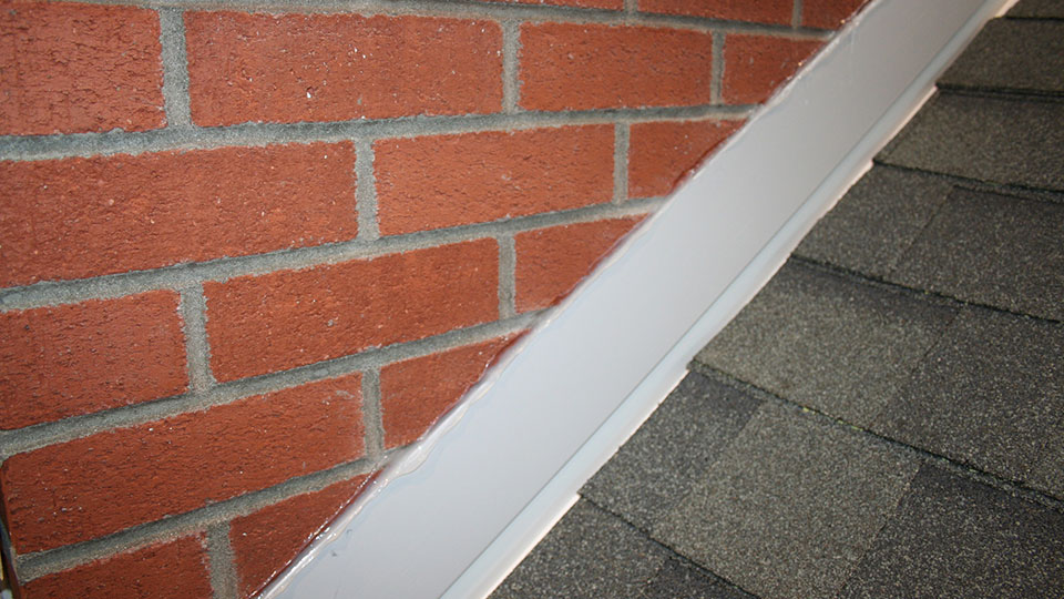
One of the issues about which I am most often contacted is water penetration into structures where brick veneer intersects with a roof – in areas such as gables, bay windows and chimneys. Some masons still do not understand that a single wythe of masonry should never be expected to be the sole provider of protection against water penetration. It is to be expected that some water might penetrate bricks, or other masonry veneer, during a wind-driven rain event.
This is a non-issue if a water-resistive building wrap and flashings are properly installed, and a relatively clear airspace is provided behind the veneer. Any water that penetrates into the wall assembly is quickly directed back to the outside. Notice how the 2012 edition of the International Residential Code (IAC) addresses what ultimately provides protection against water penetration into a home:
R703.1.1 Water resistance. The exterior wall envelope shall be designed and constructed in a manner that prevents the accumulation of water within the wall assembly by ¬providing a water-resistant barrier behind the exterior veneer as required by Section R703.2 ¬and a means of draining to the exterior water that enters the assembly.
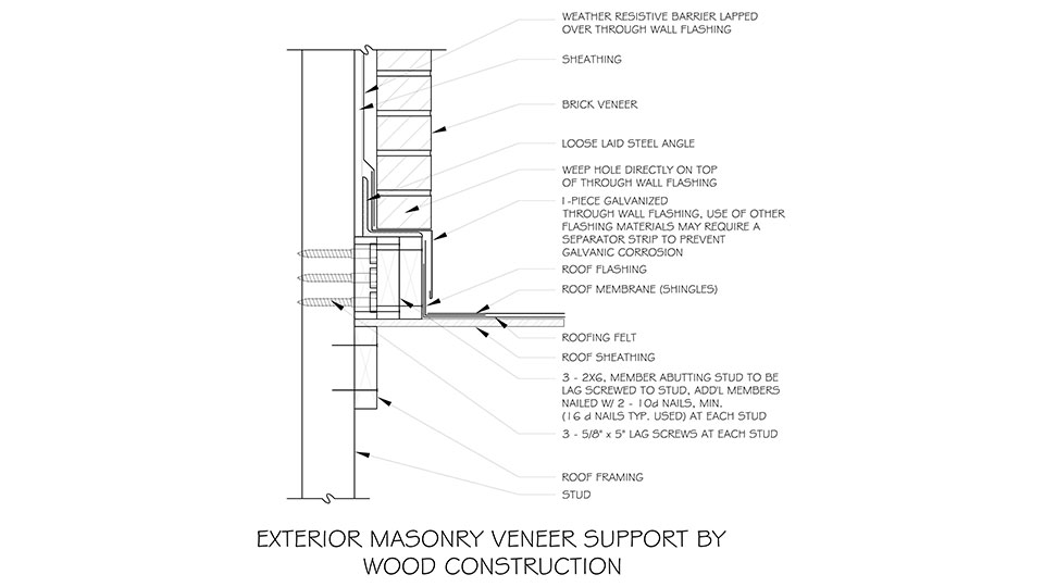
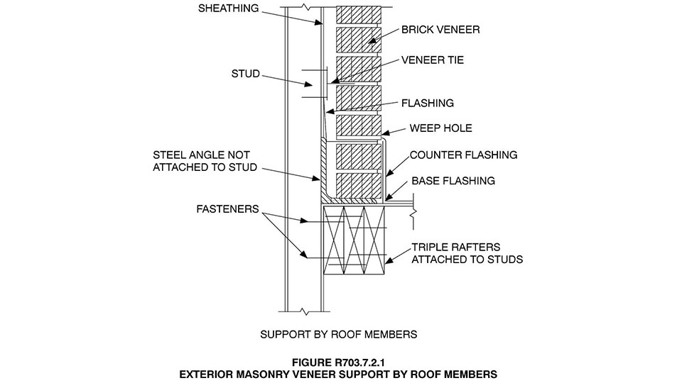
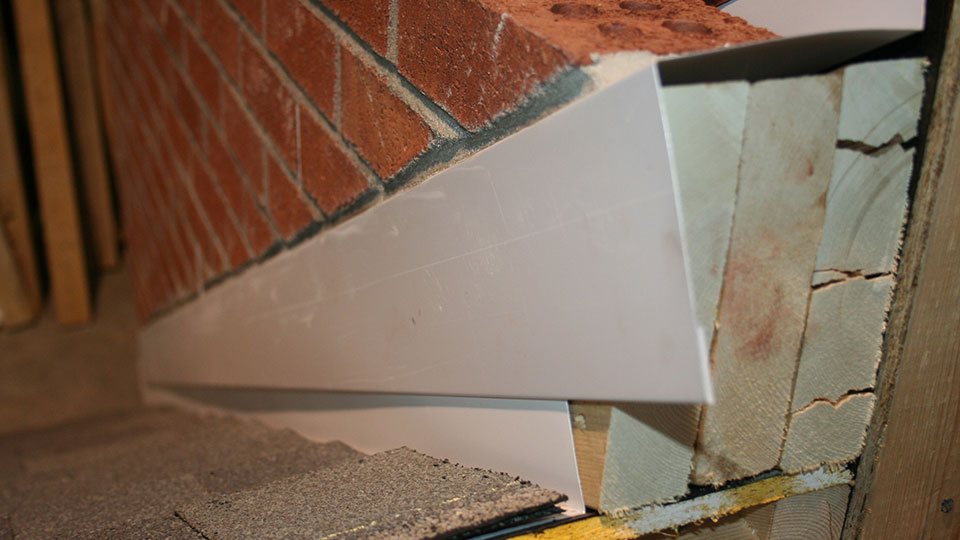
To collect water that penetrates brick veneer, and to direct it back to the exterior of the wall, Section R703.8 Flashing states, “Approved corrosion-resistant flashing shall be applied shingle-fashion…shall extend to the surface of the exterior wall finish.”
It is easy to see why such flashing is commonly referred to as thru-wall flashing. Thru-wall flashing originates with a vertical leg in contact with the exterior sheathing – tucked or shingled up under the house wrap – and a horizontal leg that extends all the way through the masonry to the exterior surface of the wall.

Introduction
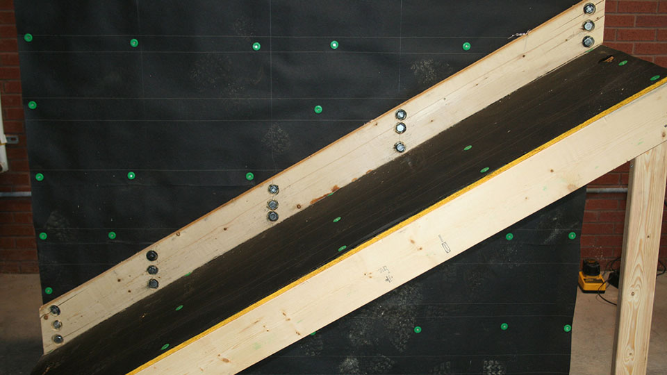
- The current flashing details in the 2013 International Residential Code (IRC) for sloped roof/wall intersections are very difficult to construct.
- As a result, most typical construction does not use any type of through-the-wall flashing which results in leaky wall complaints.
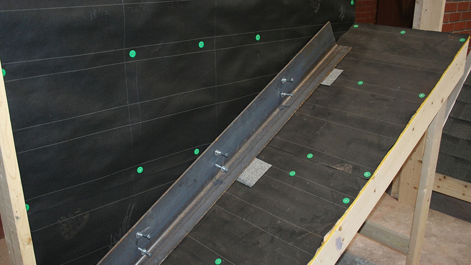
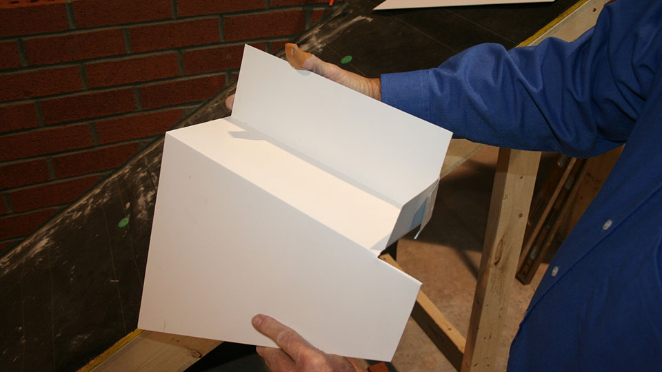
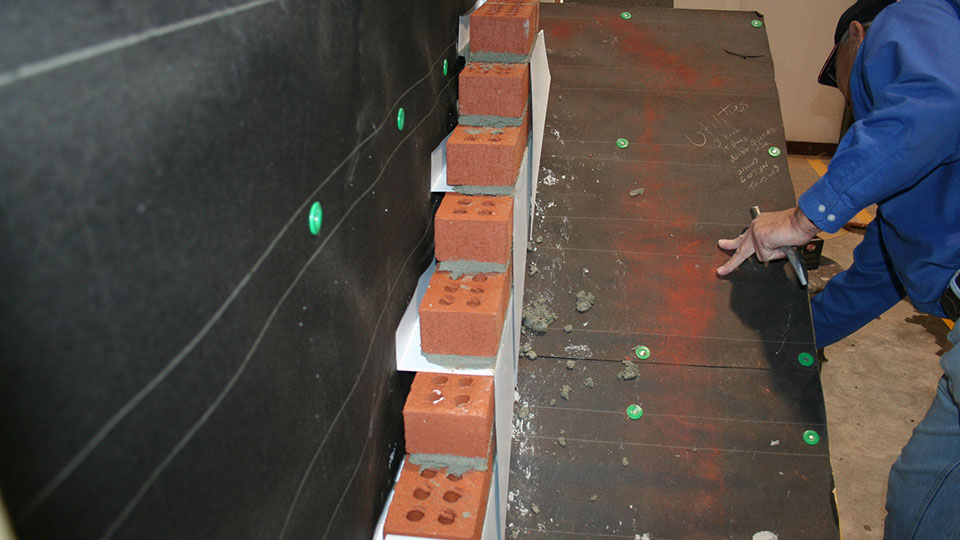
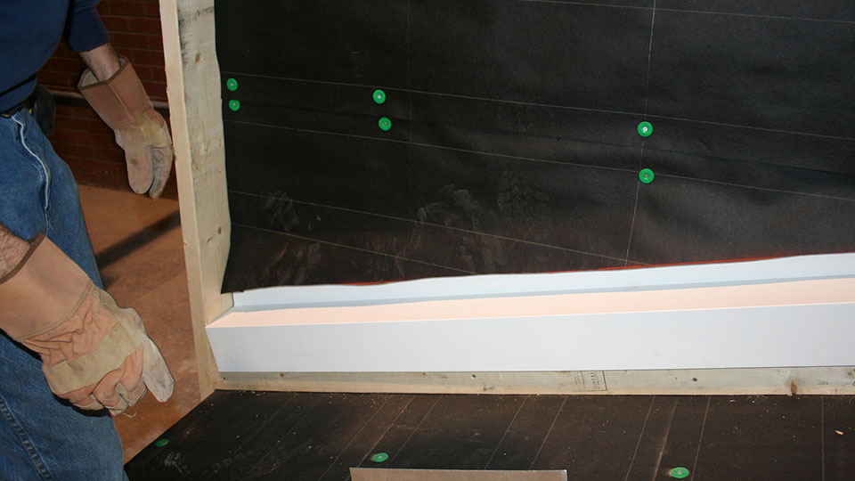
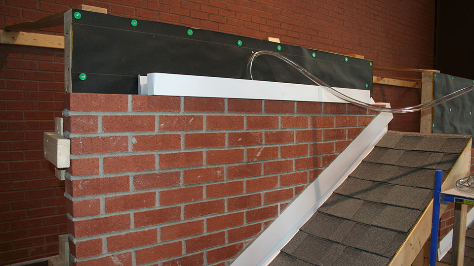
- Test panels constructed using the IRC detail and typical construction practices were built and tested in the lab.
- Additionally, an alternate flashing detail was evaluated and compared to both the IRC detail and typical construction practices.
Observations from testing
- Both the IRC and BIA-Southeast Region flashing details resisted moisture penetration.
- The typical construction practice test panel allowed water to penetrate between the roof/wall interface.
- The amount of water exiting the weeps was nearly identical between the IRC and BIA-Southeast Region details (comparing the 7:12 slopes).
- More water was absorbed by the brick for the IRC test panel than the BIA-Southeast Region test panel with equivalent slopes. This probably had to do with the slope of the actual flashing in the wall.
Summary
- A direct comparison of test panels with 7:12 roof slopes showed that both the IRC and BIA-Southeast Region test panels offered effective protection against water penetration while the typical construction test panel did not.
- No water penetration was noted on any of the test panels constructed with the BIA-Southeast Region detail.
The photos and information contained herein can only establish a partial explanation of the BIA detail and the testing that was undertaken. If you have any questions/suggestions, I would welcome your phone calls/email messages in this regard. One thing for sure, if contractors continue to encounter water penetration issues with masonry veneer applications, they will tend to lean toward using some other type of cladding material. That is the very last thing I want to see happen.
About the Author
Bryan Light is the Technical Services Director at the Brick Industry Association (BIA). Bryan has worked in the masonry industry since 1964 and joined the staff at BIA in October of 1999. He is a Gold member of the Building Officials of Georgia, and a member of the Metro Atlanta Inspectors Association. Bryan has served as the Chairman of the National SkillsUSA Masonry Technical Committee, overseeing the annual contest for secondary and post-secondary masonry students.


